
|

British Naval Heritage in Micronesia:
Tangible evidence of the armament trade from 1890 to 1937
by Dirk H.R. Spennemann
Chapter 3. Description of Six-inch (150mm) Coastal Defense Guns
|
The 150mm coastal defense guns are former naval guns set in land emplacements.
On board of a ship they had been either fitted singly in turrets or barbettes
(1895-1905) or in turrets with two or three barrels (1906-1930s). In their land
emplacements some barrels were fitted with a shield, while some lack it, such
as all six-inch guns on Mile Atoll (while the 140mm guns on Mile do have a
fitted shield).
In the following I will discuss the individual components of these guns:
barrel, breech mechanism, recoil mechanism, gun-laying equipment, gun mount and
shield. Finally the camouflage and the range finder shall be described.
The six-inch guns employed by the Japanese had a varied length of the bore:
guns of 40, 45 and 50 calibres are known to have been manufactured. To date
none of the guns emplaced in the Marshall Islands has been measured in detail.
This is planned for a future, more detailed in-depth assessment of all six inch
guns and their preservation. One gun on Mile, emplaced as a single gun in the
south, bears on the recoil mechanism and on the ring supporting the gun pivot
the number 6.45 indicating that it is a six inch gun with 45 calibre bore.
One of the guns of the north-eastern CD battery on Taroa, Maloelap has a shell
exploding in its barrel and the muzzle had been blown off. This is
not an effect which occurred after the war, as the same gun is depicted in the
U.S. Strategic Bombing Survey assessment of the damage inflicted on the base on
Taroa (1947a:163 photograph 12) showing the barrel it in the same condition.
The break shows that the barrel has been cast in two steps, first the inner
part with the lands ground in, and then covered with an outer layer.
A few of the Japanese six inch guns barrels encountered in Kiska, Aleutian
islands, had been rifled with 28 lands in contrast to the British guns
encountered at the same location which, like barrels on Wotje and Taroa, had
been rifled with 48 lands (Verbeck 1943:17).
The breech of all British guns and Japanese copies under discussion consists of
a lever-operated breech with an interrupted screw mechanism. The guns
encountered in the Marshall Islands have three types of breech blocks Both
British breech blocks have date stamps on them (1898 & 1905); further, we
can assume that the Japanese gun is a copy of the British ones, dating it to
about 1905 or later. Based on this chronological sequencing, then, there seems
to be a trend of increasing thickness and width of the breech blocks. All
breech blocks seen in the Marshall Islands have their hinges on the right hand
side of the gun. Unfortunately, from the preservation point of view, the breech
blocks have been made from a copper alloy, which made them a prime target of
scrap metal dealers. Where the breech block could be taken off completely, this
was done, while on other occasions it was sawn off .
Table 2. Ascertained breech block Numbers and dates of six-inch guns on
Mile, Taroa and Wotje
| Breechblock No. | Year | Manufacturer | Island | Location |
| 1168 A | 1905 | EOC | Mile | Southern coast, single gun |
| 1236 | | | Mile | Western coast, southern battery |
| 11377 | 1898 | EOC | Taroa | Northeastern coast |
| 11378 | 1898 | EOC | Taroa | Northeastern coast |
| 12857 | 1901 | EOC | Wotje | East coast, southern battery |
| 13828 | 1901 | EOC | Wotje | East coast, southern battery |
| 15658 | 1905 | EOC | Mile | Western coast, northern battery |
| 15668 | 1905 | EOC | Mile | Western coast, northern battery |
| 15859 (?) | 1905 | EOC | Mile | Western coast, northern battery |
The six inch guns, both of British and Japanese manufacture, had two recoil
cylinders mounted underneath the barrel. Each cylinder consists of an iron
cylinder of 6 inch diameter, containing a densely coiled spring, two copper
alloy caps, a central rod and retaining nuts. In some case the caps and nuts
have been removed by scrap metal dealers. In at least one instance the recoil
cylinder has rusted through. Recoil springs have been removed from the cylinder
and in some cases have found adaptive re-use. The recoil mechanism of the guns
contains recuperation tubes standard to all guns, Japanese, British or
American, of that period. The brass caps of the recoil cylinder bear numbers,
sometimes corresponding with the gun. These numbers can be located on the
narrow flange or on the main surface.
The range drum and the elevating wheel is located on the left side of the
breech and the transversing wheel on the right. The gun had two telescopic
sights and an electrical trigger mechanism with a pistol grip (CINPAC-CINCPOA
1945a:56).
The guns were mounted in a cradle with a sturdy pivot point. The cradle which
supports the early 150mm guns seems to have lower vertical arms than the
cradles supporting later arms. A number of different gun mounts has been used
for the guns in the Marshall Islands. While some of the mounts may well be
original mounts built for the guns when used on the British-built vessels ,
others may be Japanese-built mounts manufactured for the British guns.
The mount of two guns on Maloelap are marked "PII". In addition, a large round
cap at the side of one of these mounts bearing an English-language instruction
for filling the recoil press reads "6INCH QF MOUNT .. MARK II"
making it a British built PII/Mark II gun mount.
The intelligence information available on some guns shows that they were able
to have an elevation of up to 30deg. with ranges of up to 15,000 yards. In
actuality, however, the actual elevation of the six-inch guns depended on the
type of gun mount used. With the P VIII mounting the elevation was restricted
to only 14deg., while the P III and P IV mountings allowed for a 20deg.
elevation and hence greater range (Campbell 1984:39). The Mk. II/PII mounting
allowed an elevation of 10deg., while the PIII mounting only permitted 7deg.
The ballistic data available show that a British Mk. VII 6-inch gun, set on a
MkV mounting with 10deg. elevation could fire 21,700 yards, while the same gun
on a PIII mounting had a maximum range of 15,000 yards (MID 1945:92). The
bearing ring of the gun mount consists of a copper alloy, while the cradle and
the pivot are made of steel or cast iron. This ring is often stamped and
provides a serial number of gun mount.
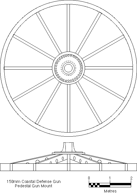
Figure 3. Sketch drawing of a pedestal mount ("spider base") for a 150mm gun on Mile,
Mile Atoll.
The gun was mounted on a pedestal mount, which consisted of a wheel-like steel
base with a elevated central "hub" (figure 3). The base consists of twelve
"spokes", which have a double-T cross-section, and which end in a heavy outer
rim. Each spoke has a number of holes punched in, or order to increase strength
and to reduce weight. The entire base section was prefabricated, transported to
the atoll where it was needed and bolted and welded together in place. This
wheel, which had a diameter of 640cm, was set into the soil without any
elaborate reinforcement of concrete as is observable in the gun positions of
the 127mm type. A similar observation can be made for the 140mm guns
encountered on Mile and for the six inch guns emplaced on Kiska, Aleutian
Islands (Verbeck 1943:17).
Some of the six inch guns have been fitted with a turret shield (figure 4). The
turrets shields employed for the six inch guns consisted of four plates which
were bolted together and bolted to the gun mount. The top plate is flat save
for a small embrasure at the rear. Both side plates are flat as well, while the
front plate is curved at the edges. There is a gun port as well as a long
horizontal opening for the gun laying. In this the turret differs markedly from
the turret employed for the 140mm CD on Mile, where the entire turret front is
rounded with an oblong gun port and two separate vision apertures. The size of
the shield could vary in thickness of armament. Modern measurements are not
necessarily reliable due to the corrosion which occurred since the end of the
Pacific War. Contemporary measurements taken on 150mm guns captured at Kiska
showed that the shield had 1.5 inch thick steel plates on the sides, a 4 inch
thick plate in the front and a 2.5 inch thick plate on the top (Verbeck
1943:17).
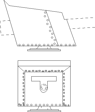
Figure 4. Sketch drawing of a turret shield for a 150mm gun on Taroa, Maloelap. Top:
side view; bottom:front view.
Not all guns in the Marshall Islands have a shield. Both 150mm gun batteries on
Taroa, and one battery on Wotje have been fitted with a shield, while none of
the 6 inch guns on Mile have them fitted. While it is possible that the turret
shields stem from decommissioned naval vessels, it is more likely that they
were custom made for use in the coastal defense installations. It is of
interest to note that the guns on Mile Atoll do not have any shields, while the
guns on the base of Taroa are all fitted with shields. In view of the later
date of construction of the Mile base it would appear that while the gun
barrels could be shipped, the turret shields were either not shipped on the
same occasion, possibly because they had not been manufactured, or were shipped
on separate ship which failed to arrive.
The individual gun emplacements were camouflaged by camouflage netting and by
camouflage vegetation in the rear areas. The guns themselves were masked by
camouflage paint markings on the gun barrels and the shield. The camouflage
netting was not considered to be effective by the U.S. dive bomber crews. Gun
emplacements could be made out easily.
The guns used a number of projectiles, the details of which are summarised
below. Both complete rounds, i.e. projectiles with propellant enclosed
in a brass casing, and ordinary shells with a powder satchel could be used. The
projectiles used were: 15 cm Complete Round (semi-fixed); 6-inch Common
(ordinary model 1); 6-inch High Explosive (ordinary type 0); 15 cm Common
(ordinary Mark 4); 15 cm Incendiary-Shrapnel and 5 cm Practice Projectile
The 15cm complete round consisted of a 29.25 inches long brass casing weighing
27 lb (empty) with a base diameter of 6.69 inches. The charge consisted of 37
DC 18.94 lbs (8.140kg), with a Mk1 case percussion primer model 4 (U.S. War
Office 1953a: 496). Primers were screwed into the cartridge case after the plug
placed there for shipping purposes had been removed (Verbeck 1943). The 6 inch
common shell (ordinary model 1) would be standard projectile for this case.
The 6 inch common (Ordinary model 1) shell measures 22.50 inches in length and
5.98 inches in diameter (at the bourrelet), weighing 39.62 kg (86.50lb). A 13th
year Mk 1 base fuse was used. (U.S. War Office 1953a:497). As propellant served
a shell casing (see above) or a bag charge.
The 6 inch High Explosive (Ordinary type 0) projectile measures 20 inches in
length (without fuse) and 6 inches in diameter (at the bourrelet), weighing
41.28kg (~90.82lb) and 44.36kg (97.59lbs) filled. A type 91 mechanical time
fuse or a type 88 mechanical point detonating fuse was used with this
projectile (U.S. War Office 1953a:498).
The 15cm Common (Ordinary Mark 4) projectile measures 22.5 inches in length and
6 inches in diameter (at the bourrelet), weighing 41.78kg (~91.9lb) and 44.42kg
(97.8lbs) filled. A type 13 Mark 1 Model 1 base fuse was used. (U.S. War Office
1953a:499).
The 15 cm Incendiary-Shrapnel projectile measures 21 inches in length and 6
inches in diameter (at the bourrelet), weighing 41.32 (~90.90lb) and 44.89kg
(98.75lbs) filled. A type 91 mechanical time fuse or a type 88 mechanical point
detonating fuzewas used with this projectile. (U.S. War Office 1953a:500).
In addition, there was the 15 cm Practice Projectile, 22.47 inches long and
weighing 100lb. The individual projectiles were between 85 and 110lbs heavy,
depending on the type of shell used. For the transport of these projectiles, as
well as the powder charges, there was a small railroad which would transfer the
ammunition from the ammunition buildings to the emplacements as needed (see
below).
Bibliographic citation for this document
Spennemann, Dirk H.R. (2000). British Naval Heritage in Micronesia: Tangible evidence of the armament trade from 1890 to 1937. Albury:
URL: http:/marshall.csu.edu.au/Marshalls/html/UKNaval/UKNaval.html
CONTACT:
Dirk H.R. Spennemann,
Institute of Land, Water and Society,
Charles Sturt University, P.O.Box 789,
Albury NSW 2640, Australia.
e-mail: dspennemann@csu.edu.au
(c) Dirk H.R. Spennemann 1993-2000
| select from the following... |
|
|
|
|
|
|
|
|
|
|
|
|
|
|
|
| |
|
|